Home / Research Notes / Note 2: Optimization-based Locomotion Planning, Estimation, and Control Design for the Atlas Humanoid Robot
Optimization-based Locomotion Planning, Estimation, and Control Design for the Atlas Humanoid Robot
by Scott Kuindersma, Robin Deits, et al, 2016, Paper Link
summarized by Peijie Xu
0. Abstract
This paper describes a collection of optimization algorithms for achieving dynamic planning, control, and state estimation for a bipedal robot.
Including footstep placement & whole-body planning and control
1 Introduction
| Task | Solution |
|---|---|
| Navigation | A footstep planner with a simple dynamic model of the robot to compute desired walking trajectories ( identify obstacles in the vicinity -> compute safe footstep regions -> find a feasible sequence of footsteps through these regions -> get a desired center of pressure trajectory through these steps) |
| Whole-body Motion Planning | A direct transcription algorithm (Section 3.2) that computes dynamically-feasible trajectories using the full kinematics and centroidal dynamics of the robot |
| Trajectory Stabilization | Combining the optimal LQR cost-to-go with the instantaneous dynamic, input, and contact constraints of the full robot inside a quadratic program (QP) |
| State Estimation | A low-drift state estimator that fuses kinematic, inertial, and LIDAR information (Section 5) |
2 Atlas
28 actuated DOF: 6 in each leg and arm, 3 in the back, and 1 neck joint
3 Motion Planning
Decompose the discrete phase into 2 parts
- Analyze the environment and compute a set of convex regions where contacts are allowed.
- Solve an optimization problem that assigns contacts to these regions in a way that minimizes cost while respecting kinematic and dynamic constraints.
Two approaches for assigning contacts to convex regions for different tasks
- footstep planning
- planning to grab handrails or transition from prone to standing
3.1 Footstep Planning as a Mixed-Integer Convex Problem
Represent the problem as single mixed-integer convex optimization, in which the number of footsteps and their positions and orientations are simultaneously optimized
Existing footstep planning methods: discrete searches and continuous optimizations. This work performs a simultaneous optimization of the discrete assignment of footsteps to convex regions and the continuous position of the footsteps within those regions.
Transform the problem of avoiding obstacles into a discrete problem of assigning each footstep to some convex region that is known to be obstacle-free
DEFINE
: the poses of the footsteps, expressed as position and yaw with
: the regions of safe terrain, represented as convex polytopes
: assignment of footsteps to safe regions
Thus, the optimization problem is:

3.1.1 Convex Decomposition (regions of safe terrain)
Require: minimize the number of convex pieces and focus on creating large convex regions

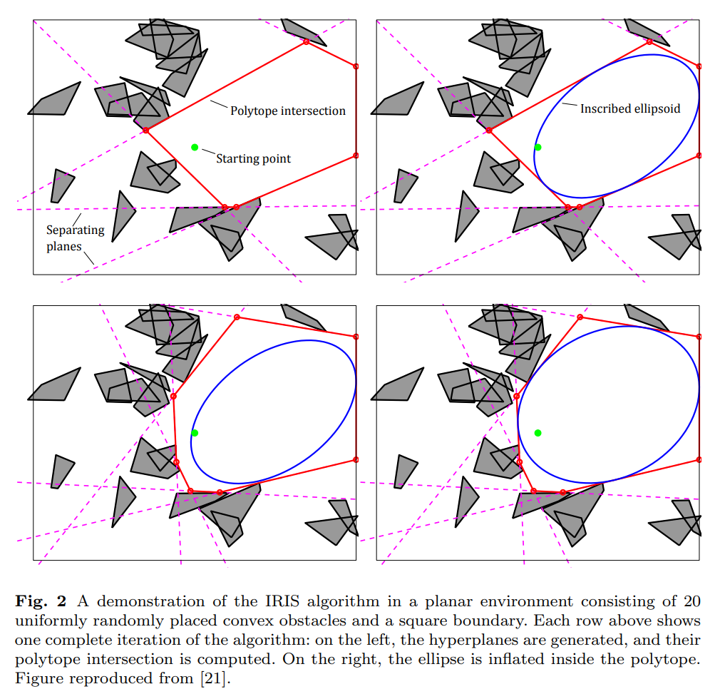
Developed IRIS[21], an algorithm for greedily computing a single large obstacle-free convex region
IRIS begins with a seed point that is known to be obstacle-free, and alternates between two convex optimizations, such point is currently provided by human pilot.
Repeat following 2 steps to grow the ellipsoid until a local fixed point is found:
- a series of small quadratic programs are solved to find a set of hyperplanes that separate the ellipsoid from the set of obstacles. Each hyperplane defines an obstacle-free half-space, and the intersection of those half-spaces is a (convex) polytope
- a single semidefinite program is solved to find the maximum-volume ellipsoid inscribed in that polytope
This paper uses the polytope as obstacle-free space, since it is always larger and can be represented as a set of linear constraints
3.1.2 Representing Reachability (poses of the footsteps)
full kinematic model of the robot
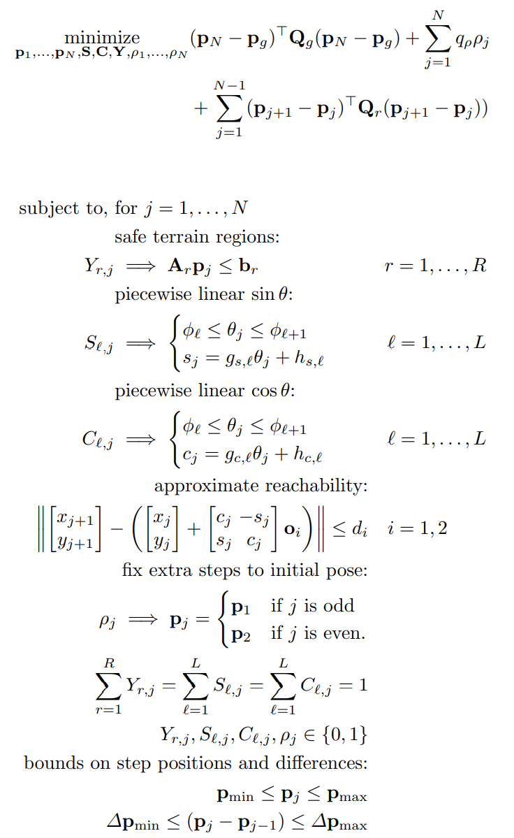
This work represents the approximate reachable set of footstep positions as the intersection of circles fixed in the frame of reference of the prior footstep.

Each circle has radius

where :
Alternatively, fix the yaw angle of each footstep beforehand, then run the mixed-integer optimization to determine the position and assignment to safe terrain for each footstep
To alternate between the following 2 steps could further refine the footstep plan: (may remove any guarantees of global optimality, but still produce acceptable footstep plans)
- using a nonlinear optimization to choose the footstep orientations
- running the mixed-integer convex optimization to choose the optimal position and assignment of those footsteps at the given orientations
When the environment is cluttered, however, the full mixed-integer convex optimization discussed above is required in order to find feasible solutions.
3.1.3 Determining the Number of Footsteps
Add a binary flag to each footstep to indicate that the particular step is unused
: if true, then footstep be fixed to the starting pose of that foot

To minimize number of footsteps
DEFINE
: goal pose
: objective weights on the distance to the goal and between steps
: objective weight on trimming unused steps
: bounds on the absolute footstep positions and their differences
: initial poses of the robot’s feet
: pre-selected piecewise linearization of the sine and cosine functions, see [22]
Then formulate the entire footstep planning optimization as follows:

3.2 Dynamic Motion Planning
DEFINE
: generalized position
: velocity
: centroidal angular momenta
: linear momenta
: centroidal momentum, the total momentum defined in a coordinate frame at the instantaneous center of mass (COM)
: COM of the robot
: total mass
:the acceleration due to gravity
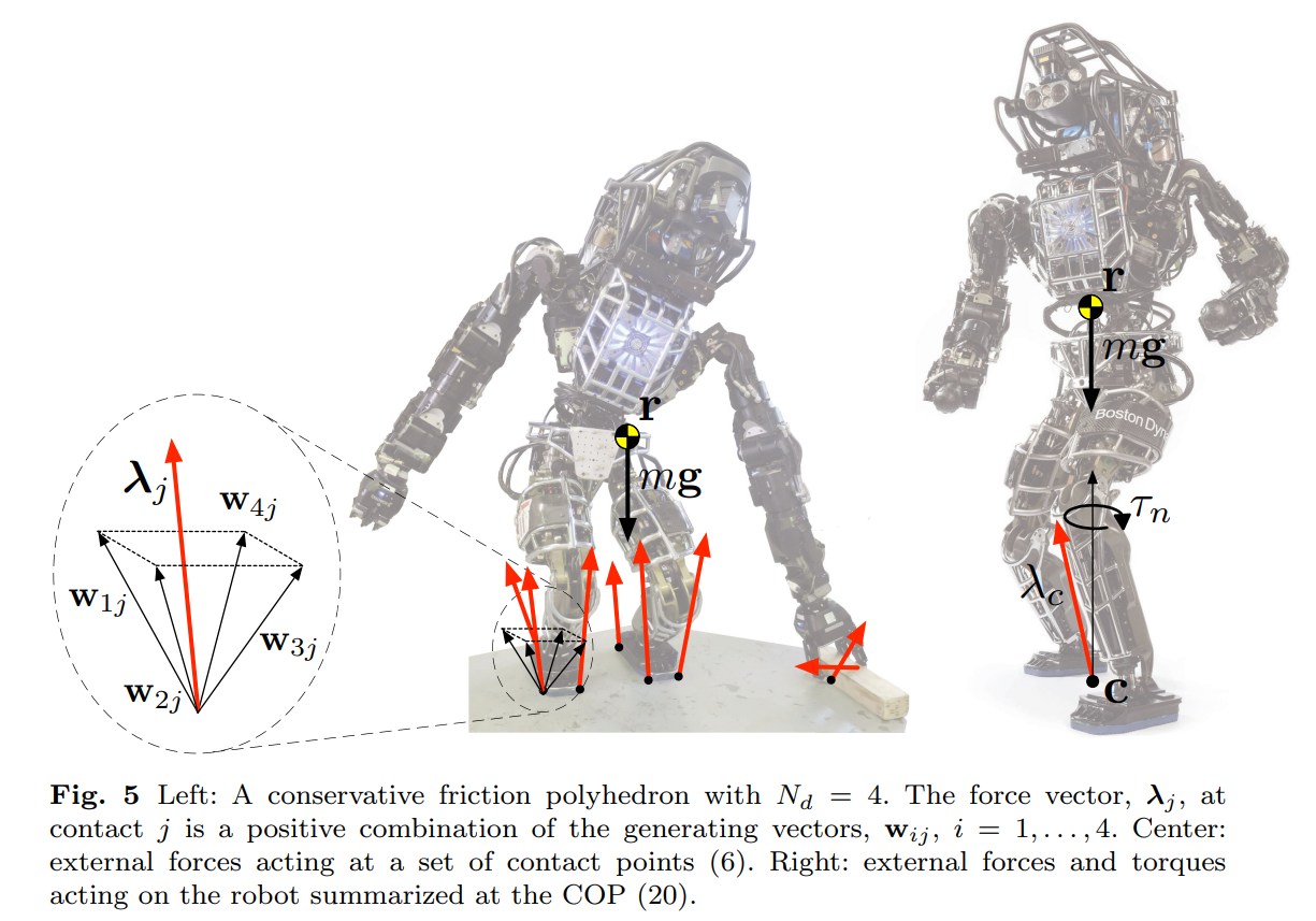
: the contact position and force at point j
: number of active contact points


There has been compelling recent work in controlling the momenta of humanoids for balance and locomotion [40, 45, 32, 38], including the resolved momentum control framework proposed by Kajita et al. [37, 53].
Assuming the robot’s

Use a friction cone for each active contact point:

where:
: the contact-surface normal : i-th tangent vector for the j-th contact point : the generating vectors : the Coulomb friction coefficient : the number of tangent vectors used in the approximation
The 2 major trajectory optimization algorithms:
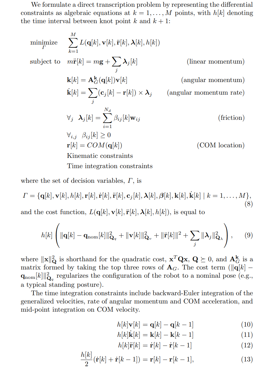
- Shooting methods involve only the control inputs as decision variables and must simulate the system forward in order to evaluate the cost function
- Transcription methods include a finite set of states along the trajectory as decision variables and incorporate the dynamics of the system as constraints on the state and input variables. By simultaneously optimizing the states and inputs along the trajectory, transcription methods avoid numerical issues that can be present in shooting methods

Similar constraint sets have been employed to control whole-body humanoid motions previously [59, 19]. Dalibard et al. [19] separately solve the kinematic planning problem using full body model and a point mass dynamic model.
4 Controller Design