Home / Research Notes / Note 1: Planning Walking Patterns for a Biped Robot
Planning Walking Patterns for a Biped Robot
by Qiang Huang et al, 2001 Paper Link
summarized by Peijie Xu
0. Abstract
| Step | Action | Result |
|---|---|---|
| 1 | formulate the constraints of the foot motion parameters | produce different types of foot motion to adapt to ground conditions |
| 2 | formulate the problem of the smooth hip motion with the largest stability margin using only two parameters | derive the hip trajectory by iterative computation |
| 3 | describe the correlation between the actuator specifications and the walking patterns through simulation studies | the effectiveness of the proposed methods is confirmed |
1. Introduction
This paper describes a proposed method for planning walking patterns, which includes the ground conditions, dynamic stability constraint, and relationship between walking patterns and actuator specifications.
2. Walking Cycle
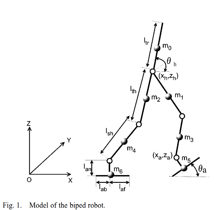
The Target Biped Robot
The humanoid biped robot with a trunk, which has 6 DOF: 3 in hip, 1 in knee, and 2 in ankle.
Biped Walking Definition
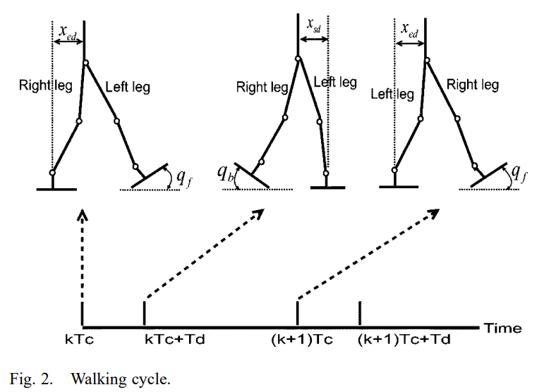
Biped walking is periodic, which is composed of 2 phases, listed below:
| Phase | Action |
|---|---|
| double-support | begins with the heel of the forward foot touching the ground, ends with the toe of the rear foot leaving the ground |
| single-support | while one foot is stationary on the ground, the other foot swings from the rear to the front |
The interval of the double-support phase in human locomotion is about 20%, the author use this value as the basis of following calculation.
Assumption
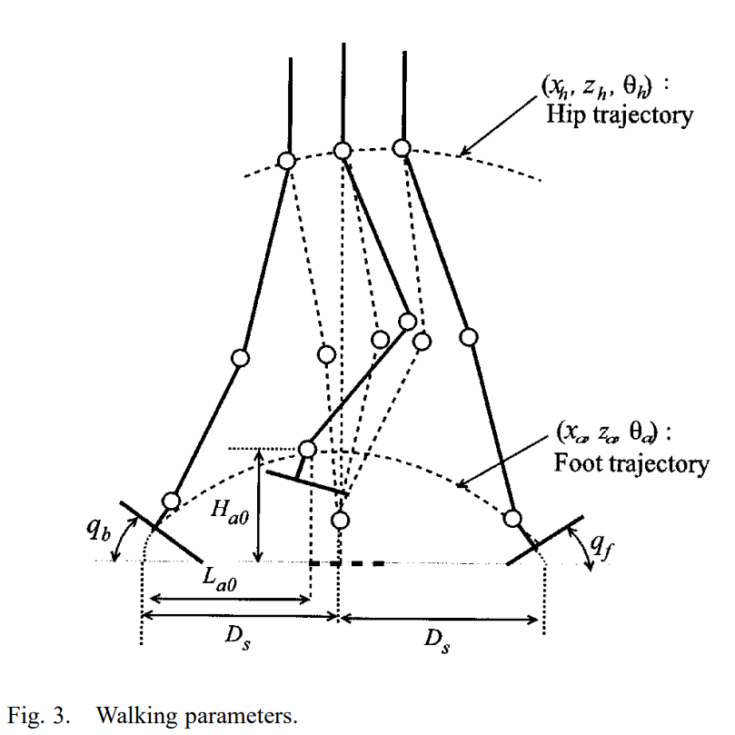
The walking pattern can be denoted uniquely by both foot trajectories and the hip trajectory.
When the robot moves straightforward, the lateral positions of both feet are constant. The lateral hip motion can be obtained similarly as the sagittal hip motion as discussed in Section IV.
In the following sections, only discuss trajectories in the sagittal plane.
DEFINE
For a sagittal plane (see Fig 1):
each foot trajectory can be denoted by a vector
, where is the ankle position, is the angle of the foot hip trajectory can be denoted by a vector
, where denotes the coordinate of the hip position and denotes the angle of the hip
We need first specify both foot trajectories, then determine the hip trajectory.
3. Foot Trajectories
In the following, only discuss the generation of the right foot trajectory, with 6+1 constraints.
DEFINE
: the period of 1 walking step
~ : time of th step k th walking step (see Fig 2): begin with the heel of the right foot leaving the ground, end with the heel of the right foot making first contact with the ground
and : angles of the right foot as it leaves and lands on the ground
Ankle Constraints

where
Kinematic Constraints

where
Foot Constraints
When
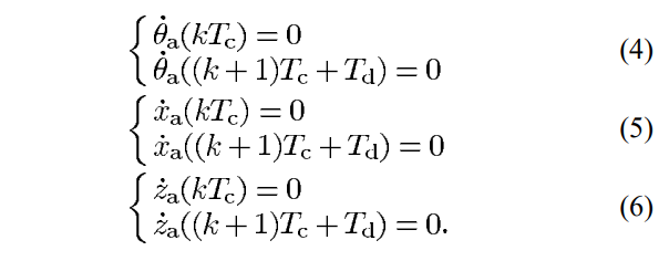
Smooth Constraints
A smooth trajectory also requires
Obtain the foot trajectory using 3rd-order spline interpolation
4. Hip Trajectory
A complete walking process is composed of three phases:
- a starting phase in which the walking speed varies from zero to a desired constant velocity,
- a steady phase with a desired constant velocity, and
- an ending phase in which the walking speed varies from a desired constant velocity to zero.
Hip motion
Assuming

Peijie:
the middle of the single-support phase should be
Should also satisfies the 2nd order continuity
2 steps:
- generate a series of smooth
- determine the final
Step 1: obtain a series of smooth
DEFINE
& : distance at the start and end of the single-support phase (see Fig. 2)
to obtain a smooth periodic

the

Step 2: determine
a smooth trajectory with the largest stability margin can be formulated as follows:

the algorithm to solve it:
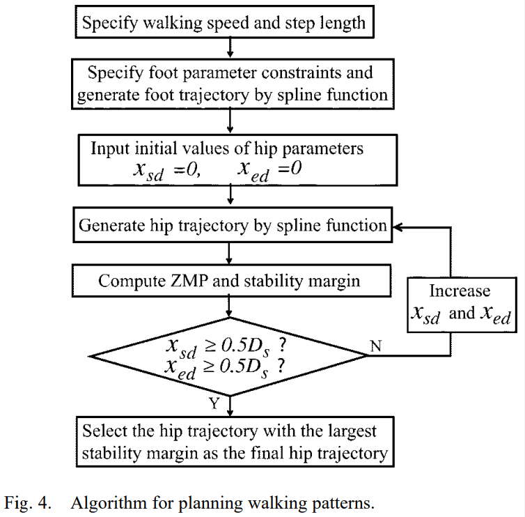
at the start and end, velocity should be 0

